
หากจะกล่าวถึงของเล่นที่มีราคาและเหมาะสำหรับบรรดานักสะสมทั้งหลายแหล ก็คงจะเป็นของเล่นที่อ้างอิงมาจากตัวละครภาพยนตร์หรือการ์ตูนดังมากมายบนจอสีอย่างแน่นอนครับ ซึ่งในวันนี้เราอยากจะพาทุกๆ ท่านไปสำรวจเกี่ยวกับ “4 ภาพยนตร์ที่มักจะถูกนำมาทำเป็นของเล่นมากกี่สุด” ที่ท่านต้องเห็นด้วยกันอย่างแน่นอนครับ วันนี้เราจะไปดูเนื้อหาคร่าวๆ ของภาพยนตร์เหล่านั้นกันครับ ภาพยนตร์ที่มักจะถูกนำมาทำเป็นของเล่น Batman เป็นซูเปอร์ฮีโรปรากฏตัวในหนังสือการ์ตูนอเมริกันตีพิมพ์โดยดีซีคอมิกส์ ตัวละครสร้างโดยศิลปิน บ็อบ เคนและนักเขียน บิล ฟิงเกอร์ และปรากฏตัวครั้งแรกในหนังสือการ์ตูน ดีเทกทิฟคอมิกส์ ฉบับที่


Recreation
Lifestyle

รูบิก ของเล่นพัฒนาสมอง
หลายๆ ท่านที่มีมักจะใช้เวลาว่างเล่นของเล่นที่สามารถฝึกพัฒนาทักษะหรือช่วยในเรื่องของสมาธิและความคิดสร้างสรรค์ทั้งหลายๆ คงจะเคยผ่านการเล่น “รูบิก (Rubik)” กันมาอย่างแน่นอนใช่มั้ยหล่ะครับ เพราะไอ่เจ้ารูบิคนี่ นับว่าเป็นของเล่นยามว่างที่ท้าทายเอาเรื่องเลยถึงขั้นมีการจับเวลาหาสถิติระดับโลกกันอย่างมากมาย วันนี้เราจะขอพาทุกๆ ท่านไปพบกับ “รูบิก ของเล่นพัฒนาสมอง” ที่น่าสนใจกันสักหน่อยครับ จะเป็นอย่างไรกันบ้างนั้น…เราไปชมกันดีกว่าครับ ทำความรู้จักกับ “รูบิค” กันสักหน่อยครับ ลูกบาศก์ของรูบิค (อังกฤษ: Rubik’s

วิธีการตั้งชื่อลูกชายให้เป็นมงคลแก่ชีวิต
ความเชื่อที่มีมาแต่โบราณเกี่ยวกับเรื่องของการ “ตั้งชื่อ” นั้น มีมากมายหลายแขนงเลยก็ว่าได้ครับ ซึ่งคนไทยสมัยก่อนแม้กระทั่งในปัจจุบันก็ต้องเลือกชื่อให้กับลูกชายหัวแก้วหัวแหวนของทุกคน วันนี้เราจึงอยากพาทุกๆ ท่านไปพบกับ “วิธีการตั้งชื่อลูกชายให้เป็นมงคลแก่ชีวิต” ที่นิยมทำมากันเนิ่นนานกันครับ จะเป็นอย่างไรบ้างนั้น…เราไปชมกันดีกว่าครับ ความสำคัญของ “ชื่อ” “ชื่อ” นั้นเป็นเสมือนเครื่องยืนยันตัวตนที่ทำให้บุคคลอื่นจดจำและเรียกขานเราได้อย่างถูกต้อง พ่อแม่บางคนมีความกังวลเกี่ยวกับการตั้งชื่อลูกเป็นอย่างมาก ถึงขนาดที่ว่าเดินทางไปหาพระ หรือเกจิอาจารย์ดังที่เคารพนับถือให้ทำการตั้งชื่อให้ เพราะว่าเชื่อว่าจะมีความเป็นมงคลและจะเป็นสิ่งที่อยู่ติดตัวลูกไปจนแก่เฒ่านั้นเองครับ หากชื่อเป็นมงคลก็คิดว่าน่าจะนำพาแต่สิ่งดีๆ เข้ามาสู่ชีวิตครับ

5 เทคนิกการเรียนที่ได้ผล
เรื่องของการเรียนหรือการศึกษาหาความรู้นั้น ย่อมต้องมีตัววัดผลต่างๆ มากมายโดยเฉพาะกับการเรียนในระดับมหาวิทยาลัยหรือระดับอุดมศึกษาที่ต้องเรียนให้จบเพื่อแลกกับใบปริญญาที่จะเป็นสิ่งเบิกทางสู่การทำงานของใครหลายๆ คนและสำคัญมากกว่าที่หลายๆ ท่านคิดเลยหล่ะครับ วันนี้เราจึงอยากมาแชร์เกี่ยวกับ “5 เทคนิกการเรียนที่ได้ผล” ที่น่าสนใจกันครับ จะเป็นอย่างไรบ้างนั้น…เราไปชมกันดีกว่าครับผม 5 เทคนิกการเรียนที่เหมาะสม เคล็ดลับในการเรียนเก่ง คือเราต้องตั้งเป้าหมานเอาไว้ในใจนั่นเอง โดยที่เราจะต้องมีการวางเป้าหมายเอาไว้ก่อนเลย ว่าต้องการเรียนเกี่ยวกับอะไร เมื่อเรียนจบในระดับชั้นมัธยมศึกษาแล้ว ค้นหาตัวเองว่าชอบอะไร สนใจอะไร และมีความฝันที่อยากจะเป็นอะไร
4 เทคนิคช่วยสอนสำหรับเด็กๆ
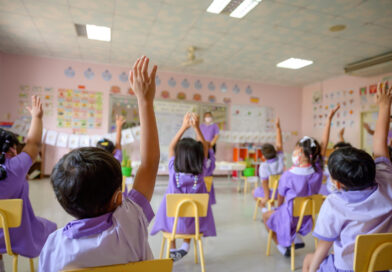
อุปสรรคของการเรียนรู้ของเด็กๆ ในปัจจุบันมีมากมายหลายอย่าง ซึ่งศัตรูตัวฉกาจเลยก็คือ “Internet และโทรศัพท์มือถือ” ที่เป็นดาบสองคำ มีทั้งประโยชน์และโทษแฝงออกมา ซึ่งทำให้เราต้องใส่ใจดูแลกันเป็นอย่างมากเลยหล่ะครับ บทความนี้จึงอยากพาท่านผู้อ่านไปพบกับ “4 เทคนิคช่วยสอนสำหรับเด็กๆ” ที่น่าสนใจเพื่อเป็นแนวทางในการส่งเสริมการเรียนสำหรับเด็กๆ กันครับ จะเป็นอย่างไรกันบ้างนั้น เราไปชมกันดีกว่าครับ ปัญหาการเรียนสำคัญกว่าที่คุณคิด ปัญหาการเรียน เป็นปัญหาสำคัญที่ควรได้รับการใส่ใจและดูแลช่วยเหลืออย่างต่อเนื่อง เนื่องจากส่งผลกระทบสูงทั้งต่อตัวเด็กเอง ครอบครัว
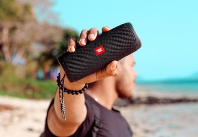
4 เหตุผลที่ทำให้เครื่องเสียง JBL เป็นที่นิยมมากในวงการเครื่องเสียง
เครื่องเสียง JBL เป็นสุดยอดเครื่องเสียงอีกยี่ห้อที่สามารถการันตีได้ถึงคุณภาพและน้ำเสียง ซึ่งทำให้ได้รับผลตอบรับเป็นอย่างมากในปัจจุบัน ในเครื่องเสียง JBL มีมากมายหลายประเภทไม่ว่าจะเป็นเครื่องเสียงชุดคอลัมน์ ลำโพงกลางแจ้ง โฮมเธียเตอร์ รวมไปถึงลำโพงบลูทูธและหูฟัง ผลิตภัณฑ์ทั้งหมดนี้เกิดขึ้นได้จากการพัฒนาและออกแบบให้เหมาะสมกับวิวัฒนาการของผู้บริโภคหรือผู้ใช้งาน ซึ่งสามารถตอบโจทย์ได้เป็นอย่างดีโดยเฉพาะชุดลำโพงบลูทูธและหูฟังยี่ห้อ JBL เราจะมาดูกันว่าอะไรที่ทำให้ชุดเครื่องเสียง JBL ถึงได้กลายมาเป็นที่นิยม มีทั้งหมด 4 ข้อดังนี้ ทั้งหมดนี้ก็เป็น
4 ปัญหาเกี่ยวกับการศึกษาสำหรับเด็กๆ
ว่ากันด้วยเรื่องของเกี่ยวกับ “เด็กเล็ก” แล้วนั้น เรื่องของการสื่อสาร พัฒนาการและการศึกษาเป็นอะไรที่สำคัญเอามากๆ เลยก็ว่าได้ครับ เพราะเรื่องเหล่านี้เป็นสิ่งจะกำหนดอนาคตของเด็กๆ เลยก็ว่าได้ครับ เพราะหากว่ารากฐานไว้ดี อะไรๆ ก็จะดีตามไปด้วยครับ วันนี้เราจะขอพาทุกๆ ท่านไปพบกับ “4 ปัญหาเกี่ยวกับการศึกษาสำหรับเด็กๆ” ที่น่าสนใจกันครับ จะเป็นอย่างไรบ้างนั้น…เราไปชมกันดีกว่าครับ การศึกษาสำหรับเด็กควรเป็นอย่างไร? ขึ้นชื่อว่าเป็นเรื่องของการศึกษาแล้ว สำหรับเด็กๆ

ทำไมไม่ควรเลี้ยงเด็กๆ ด้วยหน้าจอ
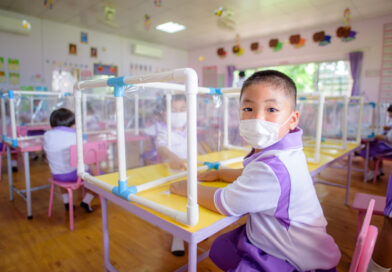
ทุกๆ ท่านเคยสักเกตการเลี้ยงลูกหลานหรือเด็กๆ ในสมัยนี้กันมั้ยครับที่จะเป็นการเอาโทรศัพท์ให้เด็กๆ นั่งดูและทำให้พวกเราเงียบไม่รบกวนการทำสิ่งต่างๆ ของพ่อแม่ ซึ่งการทำแบบนี้ในระยะยาวเด็กๆ จะมีสมาธิสั้นแถมยังติดโทรศัพท์เอามากๆ เลยหล่ะครับ บทความนี้จะพาทุกๆ ท่านไปพบกับเหตุผลว่า “ทำไมไม่ควรเลี้ยงเด็กๆ ด้วยหน้าจอ” กันครับ จะเป็นอย่างไรกันบ้างนั้น…เราไปชมกันดีกว่าครับ ระดับพัฒนาการของเด็กในช่วงต่างๆ เป็นอย่างไร? เด็กอายุ 18 เดือน เป็นช่วงวัยกำลังหัดเดิน

ทำไมเราต้องเรียนภาษาตั้งแต่เด็กๆ
ว่ากันด้วยเรื่องของการเรียนรู้แล้วนั้น หลายๆ ท่านคงเคยได้ยินเกี่ยวกับ “คนเราไม่เคยแก่เกินเรียน” กันใช่มั้ยหล่ะครับ ซึ่งเรียกได้ว่าเป็นสิ่งที่ถูกต้องมากๆ เลยหล่ะครับ วันนี้เราจึงอยากพาทุกๆ ท่านไปพบกับเหตุผลว่า “ทำไมเราต้องเรียนภาษาตั้งแต่เด็กๆ” กันครับ จะเป็นอย่างไรบ้างนั้น…เราไปชมกันดีกว่าครับ ภาษาสำคัญอย่างไร? เราสามารถบอกท่านผู้อ่านโดยสรุปถึงความสำคัญของภาษาได้ 4 ข้อหลักๆ ดังนี้ ●ภาษาเป็นเครื่องมือที่ใช้ในการสื่อสารของมนุษย์

เลือกหลักสูตรการศึกษาอย่างไรให้เหมาะสมกับเด็ก
ว่ากันด้วยเรื่องของการศึกษาแล้วนั้น…เรียกได้ว่าการที่มีการศึกษาและความรู้ที่ดีเป็นสิ่งที่สร้างโอกาสให้กับชีวิตได้มากมายกว่าผู้ที่ขาดการศึกษา อีกทั้งกระบวนการทางความคิดและการตัดสินใจของแต่ละบุคคลก็จะยุ่งยากแตกต่างกันไปอีกด้วย โดยเฉพาะการบ่มเพาะการศึกษาสำหรับเด็กๆ แล้ว หากดูแลและใส่ใจกันเป็นอย่างดี ก็จะทำให้พวกเค้าเก่งกล้าได้ในภายภาคหน้าอย่างแน่นอนครับ บทความนี้จะพาทุกๆ ท่านไปพบกับ “เลือกหลักสูตรการศึกษาอย่างไรให้เหมาะสมกับเด็ก” กันครับ เลือกหลักสูตรการเรียนให้กับเด็กอย่างไรดี หลักสูตรการเรียนรู้สำหรับเด็กๆ ถือเป็นการเริ่มต้นที่มีคุณค่าและมีความสำคัญเป็นอย่างมากเลยก็ว่าได้ครับ เพราะหากเลือกหลักสูตรที่จะกลายเป็นพื้นฐานสำหรับเด็กๆ ไม่ดีพอแล้วหล่ะก็ จะส่งผลต่อการเรียนรู้ของเด็กต่อไปในอนาคตได้ ดังนั้นควรดูจุดประสงค์ของคุณว่าจะสนับสนุนเค้าไปทางด้านไหน แต่เราขอแนะนำให้เลือกที่การเรียนรู้แบบ 2 ภาษา
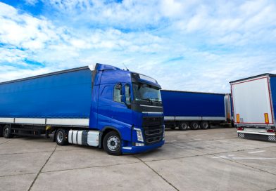
ลาล่ามูฟ การขนส่งเร่งด่วนที่สะดวกรวดเร็ว
ในสมัยก่อนหากให้กล่าวถึงเรื่องเกี่ยวกับการขนส่งสินค้า หลายคนอาจนึกถึงการขนส่งผ่านไปรษณีย์ ซึ่งทุกวันนี้ไม่ได้มีแค่การขนส่งด้วยไปรษณีย์เพียงอย่างเดียวเหมือนกันอดีต แต่มีการขนส่งด้วยรูปแบบอื่น ๆ ที่ให้ทั้งความรวดเร็วและความสะดวกแก่ผู้รับสินค้า บทความนี้จะมากล่าวถึงการขนส่งโดย ลาล่ามูฟ ซึ่งเป็นการขนส่งรูปแบบหนึ่งที่ได้รับความนิยมในปัจจุบันให้ทุกคนได้ทำความรู้จัก ลาล่ามูฟ รูปแบบการขนส่งที่เป็นที่นิยม การขนส่งสินค้าแบบ ลาล่ามูฟ เป็นการขนส่งที่ให้บริการแก่ลูกค้าทุกเวลา 24 ชั่วโมงซึ่งสามารถเรียกรถได้ตลอดผ่านทางแอปพลิเคชัน ให้ทั้งความสะดวก รวดเร็ว และบริการแบบออนดีมานด์นั่นก็คือการตามใจผู้ส่ง แล้วใส่ใจผู้รับ

การเรียนรู้ด้วยตนเอง หรือ self-learning สำคัญอย่างไรกับเด็ก
ปัจจุบันมีสื่อการสอนการเรียนรู้มากมายหลายรูปแบบ ที่ทำให้เด็กๆ จนไม่ถึงผู้ใหญ่หลายๆ ท่านได้เรียนรู้กันอย่างกว้างขวาง ซึ่งล้วนแล้วแต่เป็นการสร้างการเรียนรู้ด้วยตนเองทั้งสิ้น ซึ่งหากจะกล่าวถึง “การเรียนรู้ด้วยตนเอง หรือ self-learning สำคัญอย่างไรกับเด็ก” นั้น บทความของเรามีคำตอบให้กับนักอ่านทุกๆ ท่านกันครับ การเรียนรู้ด้วยตนเอง (Self-learning) คืออะไร? การเรียนรู้ด้วยตนเอง หรือ Self-Learning เป็นการศึกษาค้นคว้าหาความรู้

4 วิธีทำสไลม์เล่นเองง่ายๆ ด้วยอุปกรณ์ใกล้ตัว
หลายๆ ท่านเคยเห็นหรือได้สัมผัสกับเจ้าของเล่นแนววิทยาศาสตร์สมัยใหม่อย่างเจ้า Slime(สไลม์) กันมาบ้างใช่มั้ยหล่ะครับ ซึ่งเจ้าตัวนี้เป็นของเล่นที่สามารถทำได้ง่ายๆ และสะดวกมากกว่าที่ท่านคิดอีกด้วย วันนี้เราจึงขอพาทุกๆ ท่านไปพบกับ “4 วิธีทำสไลม์เล่นเองง่ายๆ ด้วยอุปกรณ์ใกล้ตัว” พร้อมกับทำความรู้จักว่า “สไลม์” นี้คืออะไรกันครับ ของเล่น “สไลม์” คืออะไร? สไลม์ หรืออีกชื่อหนึ่งคือ น้ำลายเอเลี่ยน

10 เทคนิคเรียนออนไลน์อย่างมีประสิทธิภาพ
เนื่องจากสถานการณ์ COVID-19 ที่ดำเนินมาถึงปัจจุบัน การเรียนออนไลน์จึงกลายเป็นกิจกรรมที่เราคุ้นชินกันอย่างมาก ที่ถึงแม้ว่าโรงเรียนแต่ละโรงเรียน หรือมหาวิทยาลัยต่างๆ จะเปิดเทอมมานานนับเดือนแล้วก็ตาม เพราะทุกวันนี้การเรียนออนไลน์จะกลายมาเป็นความปกติใหม่ หรือ New Normal ที่ทุกคนคงคุ้นหูกันมากในยุคนี้ ถึงแม้ว่าการเรียนออนไลน์จะง่าย และสะดวกสบายกว่าแบบปกติ แต่กลับกลายเป็นความสะดวกสบายที่ผู้เรียนเองควรจะต้องมีวินัย และความรับผิดชอบกำกับอยู่ด้วย เพราะบางทีเราอาจจะเพลิดเพลินไปกับสิ่งล่อตาล่อใจต่างๆ จนเตลิดไม่สนใจในเนื้อหาที่เรียน วันนี้เราจึงอยากขอแนะนำ “10

5 ชื่อความหมายดี เป็นศรีแก่ชีวิต
“ชื่อดีเป็นศรีแก่ชีวิต” อาจเป็นสิ่งที่อยู่คู่กับชาวไทยมาตั้งแต่เกิดก็ว่าได้ครับ เพราะไม่ว่าพ่อแม่ไหนๆ ก็ต้องการให้ลูกมีชื่อที่มีความหมายที่ดี หวังให้ลูกเจริญก้าวหน้าในอนาคตกันทุกคนอยู่แล้ว การเลือกหรือตั้งชื่อดีๆ ให้กับลูกๆ จึงเป็นสิ่งที่ต้องทำหลังจากได้ทราบว่าจะมีเจ้าตัวน้อยออกมาแล้วหล่ะครับ บทความนี้จึงอยากขอแนะนำ “5 ชื่อความหมายดี เป็นศรีแก่ชีวิต” ที่สามารถนำไปตั้งเป็นชื่อลูกๆ ก็ดีหรือจะเปลี่ยนชื่อท่านผู้อ่านในปัจจุบันก็ได้มาฝากทุกๆ ท่านกันครับ หลักการตั้งชื่อลูกที่ดีมีขั้นตอนใดบ้าง? การตั้งชื่อลูกควรผสานศาสตร์ทางภาษาและโหรา ซึ่งสามารถแบ่งออกเป็นหัวข้อต่างๆ ได้ดังนี้ ●การตั้งชื่อลูก
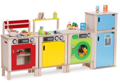
รวม 5 ของเล่นแบบไหนที่ปลอดภัยสำหรับเด็กเล็ก
ของเล่นกับเด็กเรียกได้ว่าเป็นของคู่กันเลยก็ว่าได้นะครับ เพราะของเล่นนั้นเป็นสิ่งที่เราต่างเคยผ่านการเล่นกันมาไม่มากก็น้อย มีหลากหลายแบบ อีกทั้งยังเป็นของสะสมสำหรับผู้ใหญ่บางรายได้อีกด้วยครับ และหากว่ากันด้วยขนาดและสัวดุที่ใช้ทำของเล่นสำหรับเด็กเล็กแล้ว มีเรื่องให้ต้องกังวลมากมายเช่นกันครับ บทความนี้เลยอยากจะขอแนะนำ “5 ของเล่นแบบไหนที่ปลอดภัยสำหรับลูกเล็ก” ให้กับทุกๆ ท่านได้ทราบและได้รู้ถึงประโยชน์ของการเล่นของเล่นสำหรับเด็กๆ กันอีกด้วยครับ 5 ของเล่นปลอดภัยสำหรับเด็กเล็ก แถมเสริมพัฒนาการอีกด้วย!!! 1.ตัวต่อบล้อคไม้ที่มีขนาดใหญ่พอประมาณ ตัวต่อไม้เป็นของเล่นยอดนิยมสำหรับเด็กเล็กที่สามารถเล่นได้อย่างง่ายดายแถมยังสามารถช่วยส่งเสริมทักษะการก่อสร้าง ออกแบบ ให้เด็กๆ ได้ใช้ความคิดสร้างสรรค์ในการวางบล้อคตัวต่อไม้ให้เป็นรูปทรงต่างๆ

Tmall แอพสั่งของจากจีน น่าโดน
-หลายๆคนนั้นอาจจะมีความต้องการที่จะซื้อสินค้าในราคาที่ถูกเพื่อที่จะนำมาใช้เองไม่ว่าจะเป็นสินค้าแบรนด์เนมหรือสินค้าต่างๆแต่ด้วยราคาในประเทศไทยเรานั้น บวกค่าภาษี บวกค่าอะไรแล้ว ทำให้ราคาสินค้านั้นแพงขึ้นเป็นอีกหลายเท่าตัวคนไทยหลายคนจึงนิยมสั่งของจากประเทศจีนเนื่องจากมีราคาที่ถูกและเราไม่ต้องกังวลเรื่องภาษีหรือภาษีนำเข้าก็อาจจะถูกกว่าของไทยก็ได้ทำให้คนไทยมักนิยมสั่งของจากแอพสั่งของจีนแต่หลายหลายแอพนั้นก็มีข้อดีข้อเสียที่แตกต่างกันไปวันนี้เราจึงอยากมาแนะนำแอพสั่งของจากจีนที่น่าดูรและอาจจะทำให้เราเปลี่ยนใจมาลองซื้อสินค้าจากจีนก็ได้tmall เป็นอีกหนึ่งแอพที่น่าสนใจเพราะว่าแอพสั่งซื้อของจากจีนแอพนี้มีดีอย่างไรวันนี้เราลองไปดูกันได้เลย Tmall คืออะไร -แอพสั่งของจีน Tmallเป็นอีกหนึ่งแอพสั่งของจากจีนที่น่าสนใจเนื่องจากเป็นการขายแบบB2C เหมือนกับการที่สินค้าต่างๆถูกเข้าไปในห้างสรรพสินค้าเพื่อให้เราได้ซื้อของหรือเรียกง่ายง่ายว่า แอพนี้จะนำของที่เข้าห้างสรรพสินค้านั้นมาขายในรูปแบบของออนไลน์หรือเรียกง่ายง่ายก็คือต้องมีการจดทะเบียนนิติบุคคลเครื่องหมายการค้าหรือเอกสารอื่นๆโดยข้อดีของแอพสั่งของจากจีนนี้คือลูกค้าสามารถเชื่อถือสินค้าคุณภาพและแบรนด์ที่อยู่ในแอพสั่งของจากจีนแอพนี้ได้เนื่องจากส่วนใหญ่แล้วจะเป็นทางบริษัทต่างๆนำเข้ามาขายเองมากกว่าโดยผู้สั่งซื้อจะเป็นลูกค้ากระเป๋า ที่มีกำลังซื้ออย่างมากและส่วนใหญ่เป็นลูกค้าประจำซึ่งในบางแอพนั้นอาจจะมีของปะปนได้ง่ายกว่า เนื่องจากว่าไม่ใช่ทางบริษัทมาขายเองโดยtmall จะแบ่งออกเป็นtmall global คือการนำสินค้าแบรนด์จากต่างประเทศเข้ามาขายและtmall ที่จะเป็นแบรนด์ ในจีนอย่างเดียวโดยยังมีสินค้าไทยที่เข้าไปขายในนั้นด้วยไม่ว่าจะเป็นดอกบัวคู่และmistine โดยแอพสั่งของจีนแอพนี้กลุ่มผู้บริโภคหลักจะเป็นกลุ่มลูกค้าที่อยากได้ของแบรนด์เนมหรือว่าสินค้าต่างๆที่เด่นและดังในแต่ละประเทศไม่ว่าจะเป็นสินค้าจากประเทศจีนหรือสินค้าจากประเทศไหนไหนก็ตาม ทำให้หลายหลายคนนั้นอาจจะต้องการสินค้าแบบนี้เพื่อนำมาใช้เองส่วนใหญ่
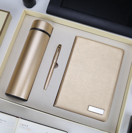
สั่งผลิตสินค้าพรีเมี่ยม มีขั้นตอนอย่างไร ง่ายนิดเดียว
อยากสั่งผลิตสินค้าพรีเมี่ยมต้องทำอย่างไร เรามีคำตอบ ข้อดีของการผลิตสินค้าพรีเมี่ยม โดยหลักๆ คือ สั่งผลิตได้จำนวนมาก ลดต้นทุน ได้สินค้าพรีเมี่ยมที่มีเอกลักษณ์เฉพาะตัว ไม่ซ้ำแบบใคร สินค้าพรีเมี่ยม ไม่ว่าจะเป็นของแจก ของแถม ของชำร่วย ของขวัญ ฯลฯ นิยมมอบให้กันในโอกาสสำคัญต่างๆ แสดงออกถึงความใส่ใจ ทำให้ผู้รับประทับใจ สินค้าพรีเมี่ยม มักถูกใช้ในเชิงธุรกิจ
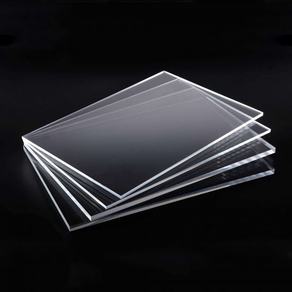
แผ่นอะคริลิคใส : มาทำความรู้จักกับแผ่นอะคริลิคใสให้มากกว่าเดิม
ทำไมแผ่นอะคริใสถึงมีราคาแพง เคยสังเกตไหมว่าทำไมแผ่นอะคริใสนั้นถึงได้มีราคาที่สูงจัง แพงกว่ากระจก และวัสดุอีกหลาย ๆ อย่าง นั่นเป็นเพราะแผ่นอะคริลิคใสนั้นทำมาจากแผ่นพลาสติกใสชนิดหนึ่ง ซึ่งมีลักษณะเป็นแผ่นเรียบ ผลิตจากน้ำยาที่เรียกว่า MMA (Methyl Methacrylate) และนำไปหล่อด้วยความร้อนสูง ซึ่งประโยชน์ด้านการใช้งานของแผ่นอะคริลิคใสนี้ก็สามารถทำได้หลายอย่างเลย ทั้งดัดให้มีรูปร่างต่าง ๆ ตามที่ต้องการก็ย่อมได้ และสามารถผลิตให้มีความหนาตามกำหนดได้ ตั้งแต่หนา 2

วิธีเลือกซื้อรถให้ตรงกับไลฟ์สไตล์ เลือกแบบไหนเหมาะสมกับตัวตนของคุณ
ในแต่ละปีก็จะมีรถยนต์รุ่นใหม่ ๆ เปิดตัวออกมายั่วใจของเราอยู่โดยตลอด ซึ่งแต่ละรุ่นที่ออกมามีทั้งความสวยงามดีไซน์ล้ำ ๆ มีทั้งเทคโนโลยีทันสมัยที่ตอบโจทย์การขับขี่ในยุคใหม่ รวมถึง Option ที่น่าสนใจอีกมากมาย จนทำให้เราไม่สามารถหักห้ามใจที่จะหาโอกาสซื้อรถคันใหม่ได้ ทั้ง ๆ ที่รู้ว่าได้รถใหม่มาก็ต้องมีการซื้อประกัน รถใหม่ที่เหมาะสม รวมไปถึงค่าใช้จ่ายจิปาถะอื่นๆ ที่จะตามมา แต่หลายคนก็ยอม แต่ก่อนที่คุณจะตัดสินใจเลือกรถรุ่นใหม่ มีสิ่งหนึ่งที่คุณควรรู้ก่อนว่ารถรุ่นใหม่ทุกรุ่นทุกคันที่ออกมา ใช่ว่าจะเหมาะสมกับสไตล์การขับขี่ของทุกคน
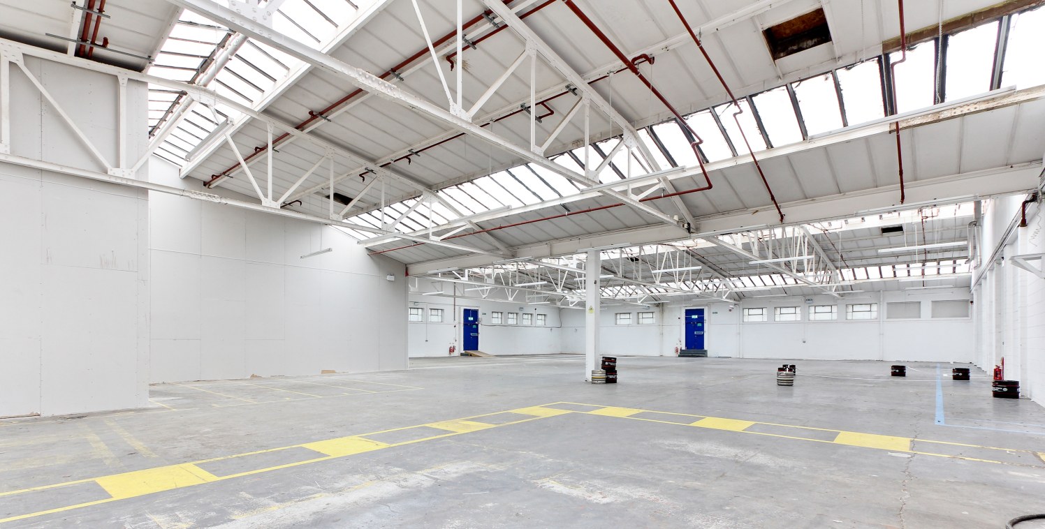
เรื่องน่ารู้เกี่ยวกับการเช่าโรงงาน
ปัจจุบันนี้การเริ่มต้นทำธุรกิจเองถือเป็นสิ่งที่หลายๆ คนชื่นชอบกันเป็นอย่างมาก เนื่องจากว่าเทรนด์ปัจจุบัน ส่วนใหญ่แล้วจะเน้นไปที่การเป็นเจ้านายของตนเอง ทั้งนี้ก็เพราะว่าทุกคนล้วนแล้วแต่อยากจะเติบโตมากยิ่งขึ้น แต่อย่างไรก็ดี สำหรับใครที่กำลังลังเลใจอยู่ว่าจะทำอย่างไรจึงจะทำธุรกิจทางด้านโรงงานให้คุ้มค่ามากที่สุด มีคำแนะนำมาฝากดังต่อไปนี้ 1.ความคุ้มค่าในการเช่าโรงงาน สำหรับสิ่งแรกที่อยากแนะนำให้หลายๆ คนพิจารณามากที่สุดก็คือการเลือกความคุ้มค่าในการเช่าโรงงาน เพราะโรงงานที่ดีจะต้องตอบโจทย์เราในทุกด้าน ไม่ว่าจะเป็นขนาดของโรงงานที่มีความเหมาะสม รวมไปถึงการเลือกโรงงานที่อยู่ไม่ไกลจากแหล่งความเจริญ หรือสิ่งอำนวยความสะดวกต่างๆ เราต้องดูด้วยว่าการเช่าในครั้งนี้จะคุ้มค่ากับเงินที่ลงทุนหรือไม่ เพราะหากว่าไม่คุ้มค่าก็แน่นอนว่าจะทำให้หลายๆ คนเสียเงินเปล่าได้เลยทีเดียว 2.การป้องกันอัคคีภัย อันดับต่อไปที่ต้องพิจารณาก็คือการป้องกันอัคคีภัย

พิษจากการสูบบุหรี่ไฟฟ้า…อันตรายกว่าที่คุณคิด
โดยส่วนใหญ่ผู้จำหน่ายบุหรี่ไฟฟ้า จะสร้างภาพลักษณ์ให้บุหรี่ไฟฟ้าเป็นผลิตภัณฑ์ทางเลือกที่ปลอดภัยกว่าบุหรี่ทั่วไป และให้ข้อมูลที่ว่าทำให้ผู้สูบเจ็บป่วยน้อยลง โดยข้ออ้างเหล่านี้สวนทางกับข้อมูลการสำรวจพฤติกรรมการสูบบุหรี่ของประเทศไทย ที่กล่าวถึงประเด็นโทษของบุหรี่ไฟฟ้าที่ส่งผลกระทบต่อสุขภาพและสังคมของประเทศไทยว่า ในน้ำยาบุหรี่ไฟฟ้าที่ใช้ เมื่อเข้าสู่ร่างกายจะไปกระตุ้นระบบประสาทส่วนกลาง เพิ่มความดันโลหิต เพิ่มอัตราการเต้นของหัวใจและการหายใจ เพิ่มความเสี่ยงของการเกิดมะเร็งปอดโรคเกี่ยวกับทางเดินหายใจมะเร็งช่องปากได้ กระบวนหลักในการทำงานของบุหรี่ไฟฟ้า บุหรี่ไฟฟ้าที่เป็นระบบให้ความร้อนจากขดลวดไฟฟ้า โดยสามารถเลือกปรับระดับได้ จึงทำให้เกิดไอละอองสีขาวของน้ำยาบุหรี่ไฟฟ้านิโคตินได้ละเอียดและมากขึ้น ซึ่งเป็นผลให้ผู้สูบได้รับนิโคตินเข้าสู่ร่างกายเพิ่มมากขึ้นไปด้วย และไอละอองสีขาวเหล่านี้แม้มีกลิ่นหอม แต่ก็ประกอบด้วยฝุ่นขนาดเล็กกว่า pm2.5 ที่สูงกว่าไอเสียจากรถยนต์ โดยสูงถึง

มองหาการรับทำความสะอาด ที่ตอบโจทย์ถูกและดี
สำหรับธุรกิจ รับทำความสะอาด เป็นอีกหนึ่งธุรกิจ ที่น่าจับตามองเป็นอย่างมากในปัจจุบัน เลยก็ว่าได้เนื่องจากไลฟ์สไตล์ ของชีวิตคนเราที่เป็นอยู่ในปัจจุบันนี้ ค่อนข้างที่ต้องเร่งรีบจนทำให้ไม่มีเวลาในการดูแลเอาใจใส่ที่อยู่อาศัยมากมายนัก โดยเฉพาะอย่างยิ่งการทำความสะอาดบ้าน เป็นอะไรที่เรียกได้ว่าแทบจะไม่มีเวลาเลยกับ การปรับเปลี่ยนพฤติกรรมเหล่านี้ จึงทำให้ธุรกิจอะไรเหล่านี้ค่อนข้างมีความชัดเจนและดูเหมือนว่าจะเป็นอีกหนึ่งจุด ที่เต็มไปด้วยสิ่งต่างๆที่เป็นสาระ และความพร้อมที่ดูเหมือนจะเป็นอะไรที่ค่อนข้างมีความลงตัวที่ชัดเจนที่ดีได้ อย่างลงตัวที่สุดเท่าที่จะมากได้อีกครั้ง ดูเหมือนจะเป็นอีกหนึ่งสิ่งที่ง่ายและมีความพร้อม และดูเหมือนเป็นอะไรที่ค่อนข้างมีความชัดเจนที่ดีได้ ย่างแน่นอนที่สุดเท่าที่จะมากได้อีกด้วย รับทำความสะอาด จึงเป็นอีกหนึ่งสิ่งที่น่าค้นหา หากคุณมองหาจากทางจัดการค้นหาตามเว็บไซต์ทั่วไปก็จะดูเหมือนว่ามีมากมาย
Life Style ตกแต่งภายในแบบไหนที่ใช่สำหรับตัวคุณ
การออกแบบตกแต่ง ภายใน นั้นเชื่อว่าเกิดจากความชอบของเจ้าของห้อง หรือ เจ้าของบ้านอย่างแน่นอน ซึ่งความชอบของแต่ละคนนั้นก็ค่อนข้างจะแตกต่างกัน ดังนั้นในบทความนี้เราจะมาพูดถึงความชอบของแต่ละคนกันดีกว่าครับว่าออกแบบ ตกแต่ง ภายใน แบบไหนที่ใช่สำหรับตัวคุณกันบ้าง ? Style Loft Life Soft นั้นเป็นสไตล์ที่เราเห็นบ่อย ๆ ตามร้านคาเฟ่ต่าง ๆ ซึ่งสไตล์นี้จะให้ความสำคัญกับโครงสร้างของสถาปัตยกรรมเป็นหลัก
สิ่งที่เราควรรู้ก่อนจะเริ่ม “หางาน” เพื่อประโยชน์ของตัวคุณเอง
ในการใช้ชีวิตนั้น งานถือเป็นสิ่งสำคัญเช่นเดียวกัน เพราะถ้าหากมีงานนั้นจะต้องมีรายได้ที่แน่นอน แต่บางครั้งการหางานนั้นอาจจะไม่ใช่เรื่องที่ง่ายนะครับ ดังนั้นในบทความนี้เราอยากจะขอพูดถึง สิ่งที่เราควรรู้ ก่อนที่จะเริ่มหางาน เพื่อประโยชน์ของตัวคุณเองนะครับ จังหวัดที่อยู่มีอาชีพอะไรบ้าง ไม่ใช่ว่าทุกจังหวัดจะมีในทุกอาชีพนะครับ บางจังหวัดนั้นอาจจะมีบางอาชีพ และ ไม่มีอีกหลาย ๆ อาชีพก็ได้ยกตัวอย่างเช่น นักออกแบบ ส่วนมากนั้นจะทำงานอยู่ที่จังหวัดกรุงเทพแลปริมณฑลเท่านั้น ส่วนรอบนอกในต่างจังหวัดก็อาจจะมีบริษัทกราฟฟิคแต่น้อย ดังนั้นเราจะต้องดูก่อนว่าอาชีพอะไรที่เราต้องการจะประกอบอาชีพ และ
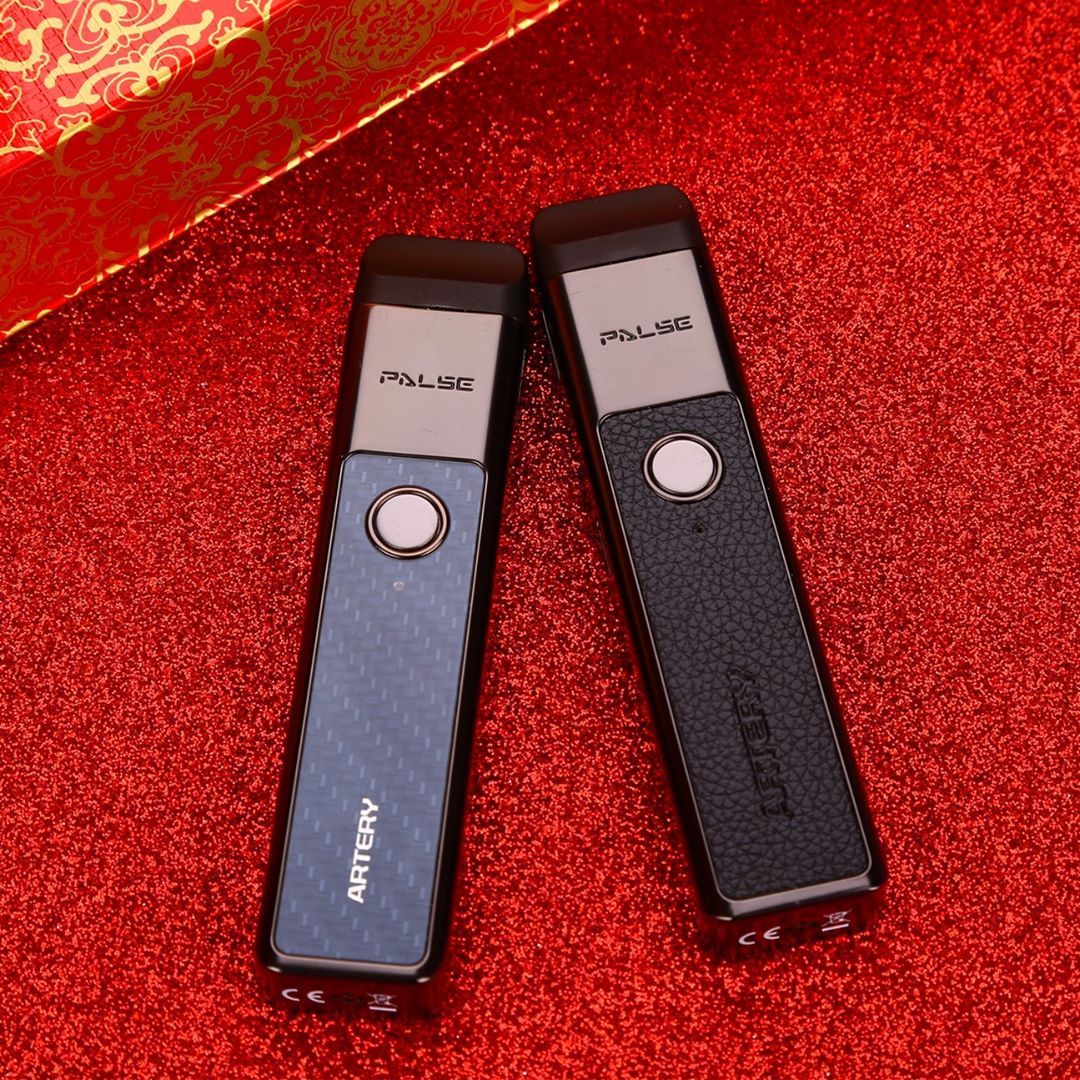
รู้จักกับ บุหรี่ไฟฟ้า (pod system) ความนิยมที่พุ่งมากขึ้น
ปัจจุบันนั้นบุหรี่ไฟฟ้านั้นกำลังเป็นที่นิยมอย่างมากในปัจจุบัน ถึงแม้ว่าบุหรี่ไฟฟ้านั้นปัจจุบันนั้นจะยังไม่ถูกต้องตามกฎหมายอยู่ แต่ว่าปัจจุบันนั้นการสูบบุหรี่ไฟฟ้านั้นก็ยังเป็นที่นิยมอย่างมากในปัจจุบัน และปัจจุบันการพัฒนาบุหรี่ไฟฟ้าก็พัฒนามาเรื่อย ๆ จนปัจจุบันนั้นการดูดบุหรี่ไฟฟ้าแบบ Pod นั้นเป็นที่นิยมอย่างแพร่หลายเราจะมาทำความรู้จักกับ พอทบุหรี่ไฟฟ้า กันให้มากขี้ดีกว่าครับ บุหรี่ไฟฟ้า Pod System คืออะไร ? เนื่องจากว่าบุหรี่ไฟฟ้าแบบเก่า ๆ นั้นจะมีขนาดที่ใหญ่เกินไปทำให้การพกไปมาไหนนั้นไม่สะดวก